product-combination-variable-speed-lathe-and-milling-machinetu240x550mm, product-combination-variable-speed-lathe-and-milling-machinetu240x550mm, /combination-machine
EN
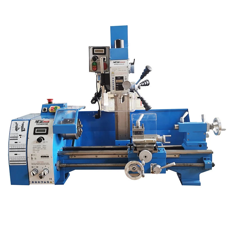
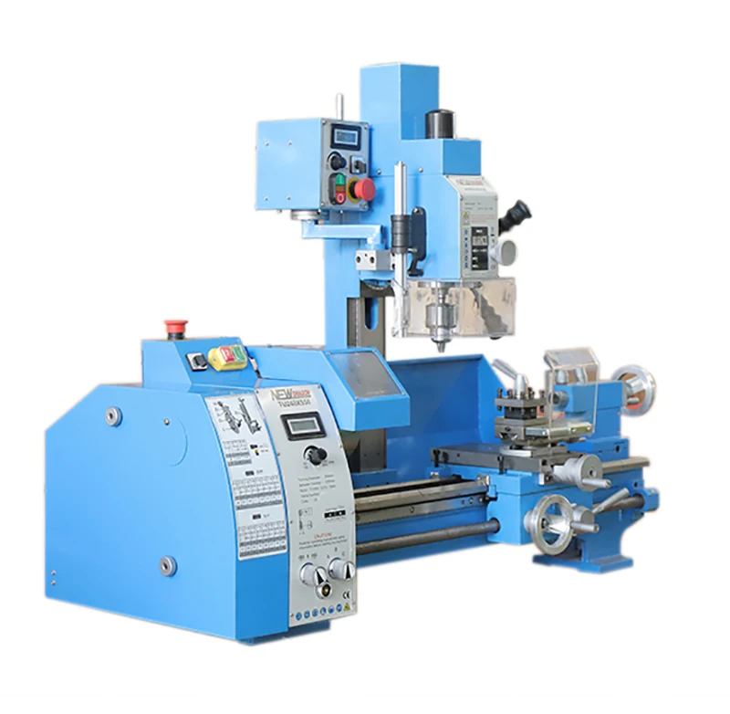
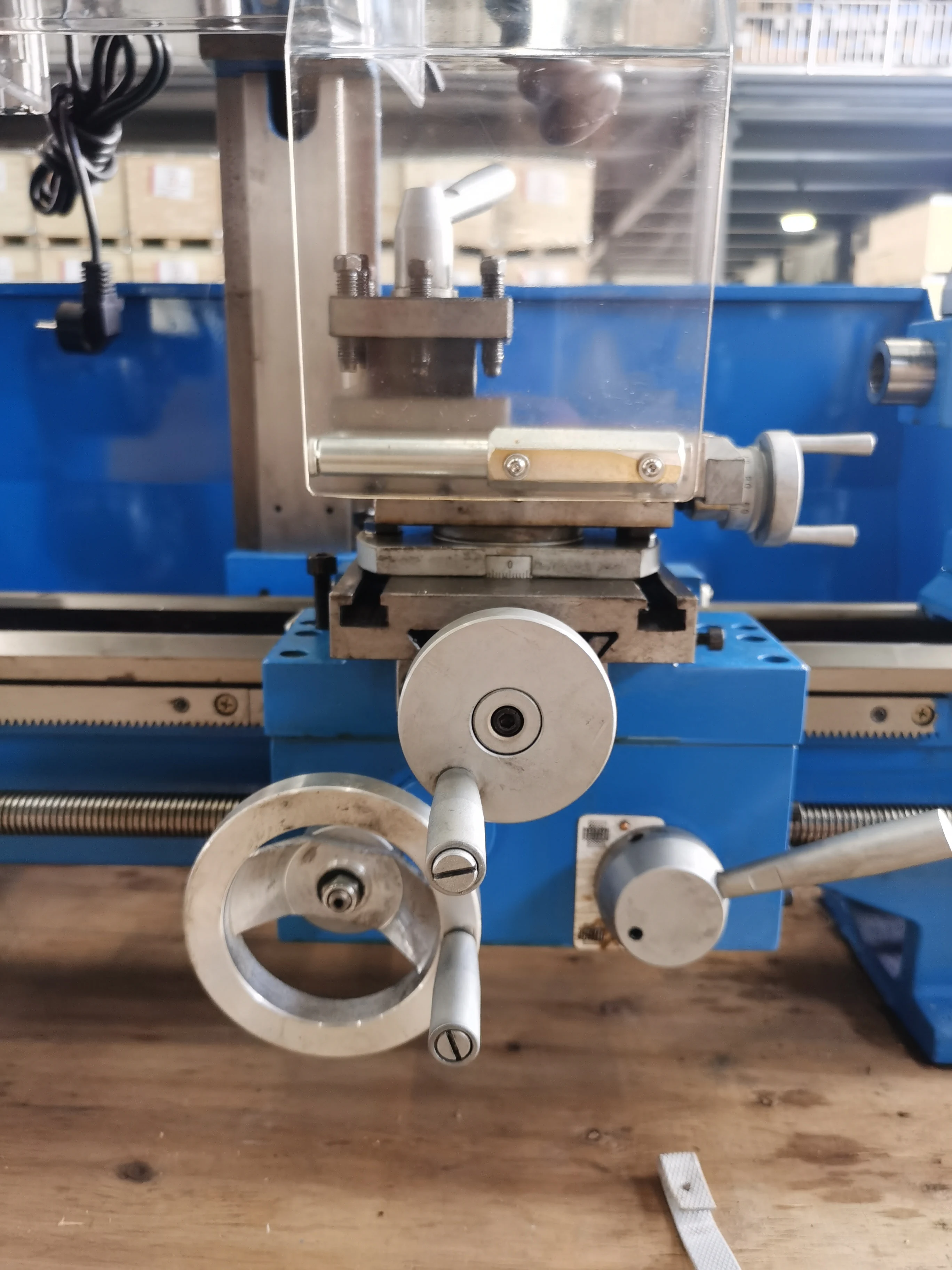
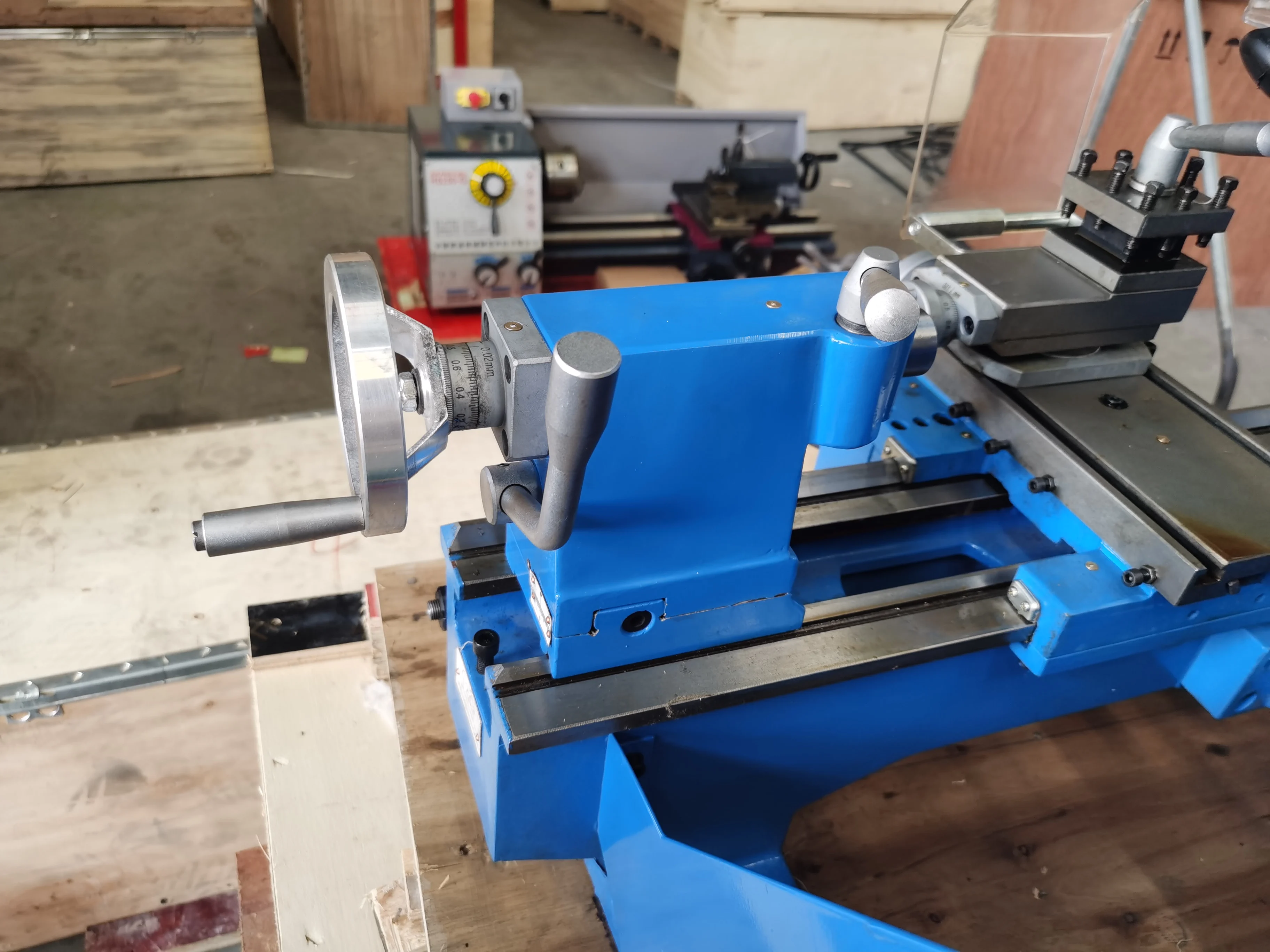
This combined lathe and milling machine is supplied as model TU240. It brings turning, drilling, and milling functions into one machine layout for workshops that need several basic metalworking operations close together. The supplied information identifies a maximum swing over bed of 250 mm and a distance between centres of 550 mm. Those figures are useful starting points when comparing the machine with the size and shape of planned workpieces. Selection should still be based on the complete operation, including material, tooling, holding method, required finish, available space, and electrical arrangement.
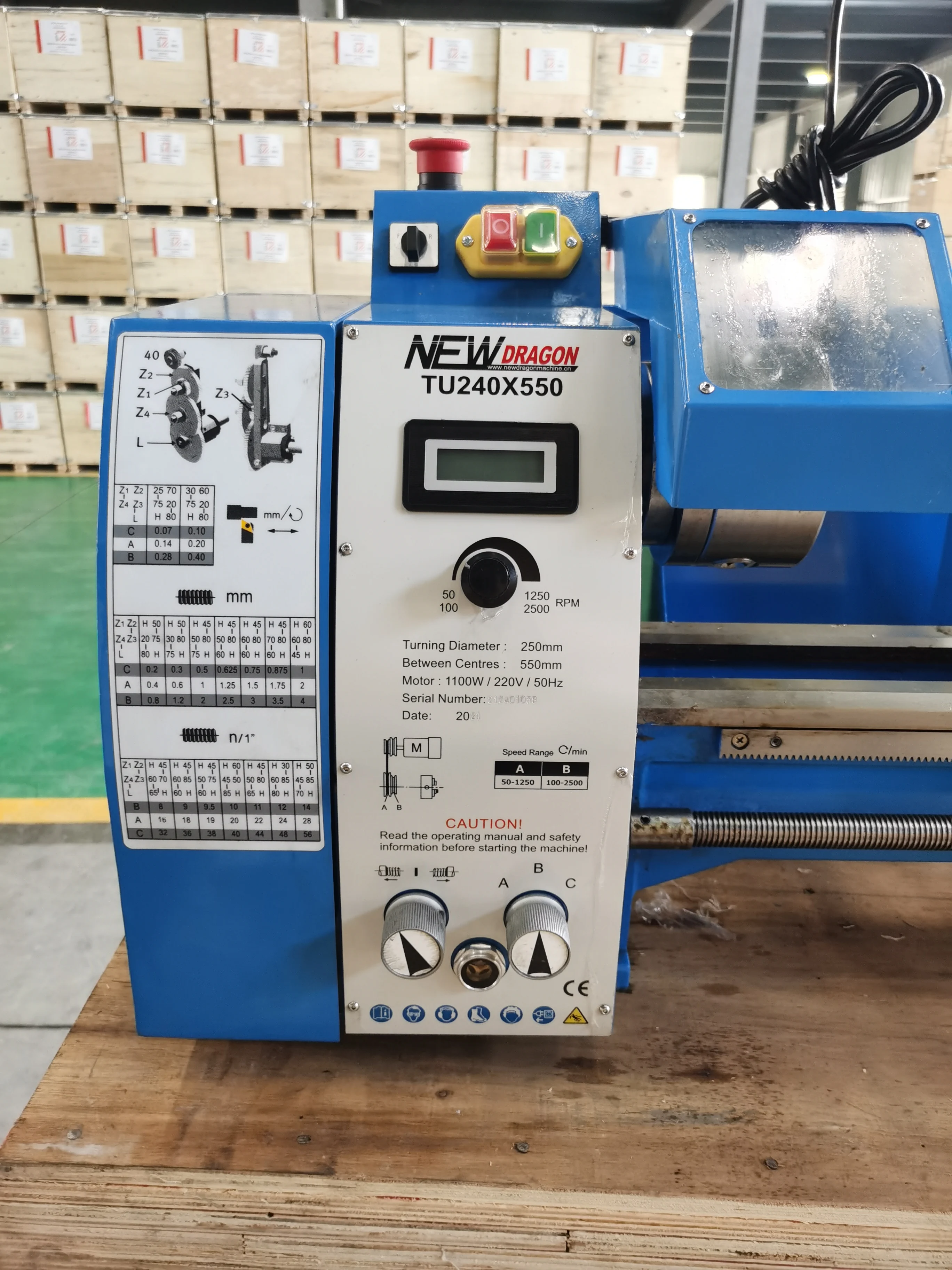
The turning section lists a 150 mm swing over the cross slide and a bed width of 135 mm. The spindle bore is listed as 26 mm with an MT4 spindle-bore taper. Listed spindle speeds are 50–2500 rpm. Longitudinal feed is specified at 0.07–0.40 mm per revolution. The thread ranges shown in the product data are 8–56 TPI for inch threads and 0.2–4 mm for metric threads. The material also lists an 1100 W motor. These are source specifications; the appropriate speed and feed depend on workpiece material, tool condition, setup rigidity, and the intended cut.
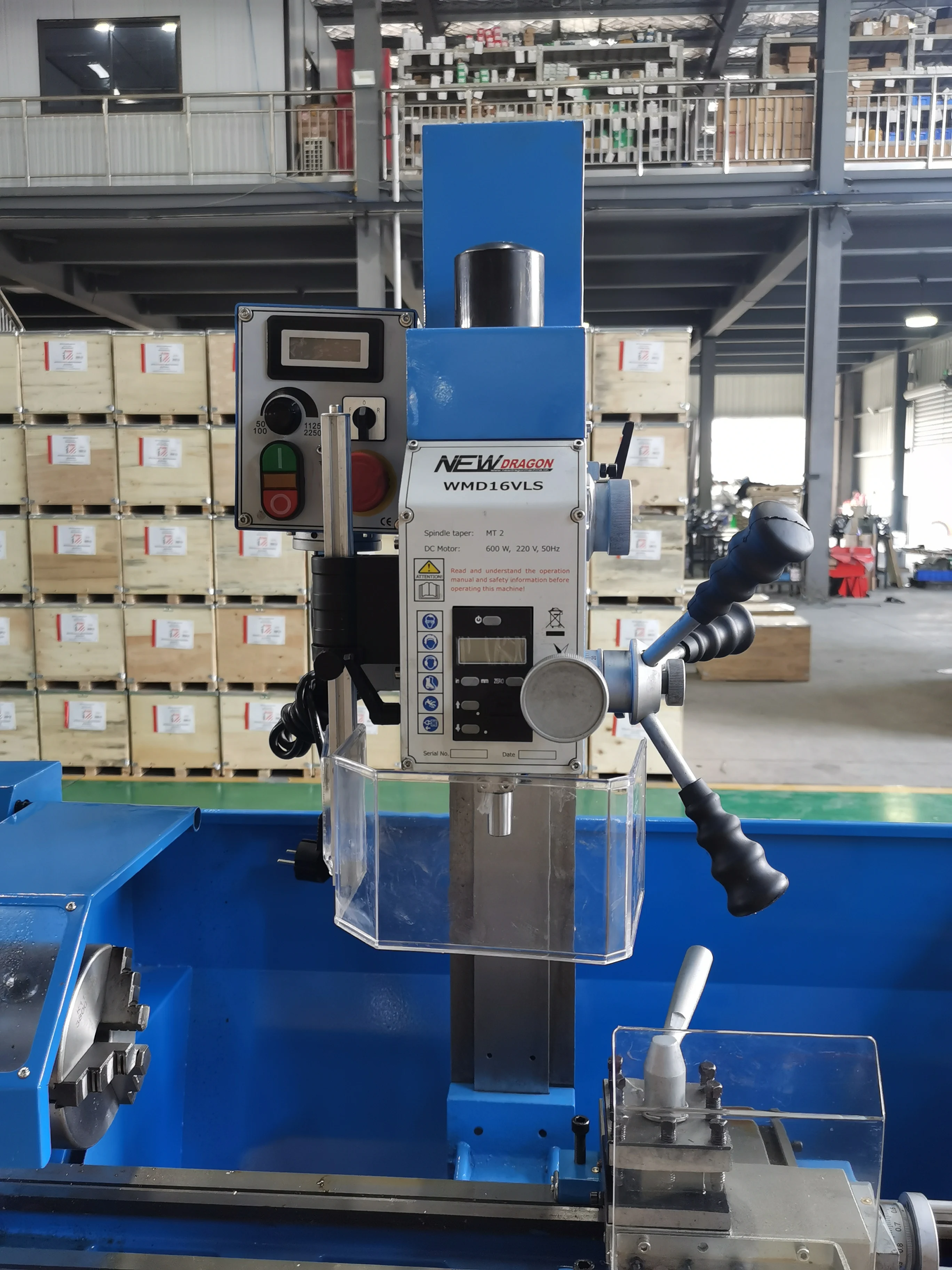
The drilling and milling head is listed with maximum drilling capacity of 16 mm, maximum cutter-head milling capacity of 52 mm, and maximum end-mill capacity of 16 mm. Other listed values are MT2 taper, 52 mm sleeve travel, 10 mm T-slot size, 50–3000 rpm speed range, 280 mm maximum spindle-to-table distance, 175 mm working range, and 600 W motor power. A high listed speed is not automatically the best choice for every task. The cutter type, workholding, material, and required surface finish should determine the practical setup.
These descriptions help explain the configuration, but production results are affected by installation, maintenance, measurement method, tooling, workpiece geometry, vibration, and operator practice. Buyers with a tight tolerance requirement should confirm the exact acceptance method and perform an application-appropriate check rather than relying on a single catalogue value.
| Model | TU240 |
|---|---|
| Maximum swing over bed | 250 mm |
| Distance between centres | 550 mm |
| Swing over cross slide | 150 mm |
| Spindle bore | 26 mm |
| Lathe motor power | 1100 W |
| Maximum drilling capacity | 16 mm |
| Maximum cutter-head milling capacity | 52 mm |
| Maximum end-mill capacity | 16 mm |
| Packing dimensions | 1200 × 580 × 1060 mm |
| Net/gross weight as listed | 180 kg |
The combined layout can suit small-batch work, maintenance tasks, training environments, and workshops where turning plus basic drilling or milling operations are needed in a compact arrangement. For a shaft, bushing, fixture, or other cylindrical component, compare its dimensions with the listed swing and between-centres capacity before ordering. For drilling or milling work, also examine cutter clearance and table setup. This is general application guidance, not a statement that the machine is qualified for every material, regulated process, or production volume.
Before purchase, check local voltage and frequency, the intended power connection, floor capacity, handling method, and clearance for operation and maintenance. The nameplate OCR includes 1100 W / 220 V / 50 Hz; confirm the delivered electrical configuration with the supplier because regional configurations and accessories require verification. Check that existing chucks, centres, tooling, cutters, drill chucks, and fixtures are compatible with the stated tapers and capacities. A paper specification should be combined with a practical review of the actual job.
The supplied description lists standard accessories including a speed display, 3-jaw 125 mm chuck, splash guard, chip pan, chuck protection cover, tool-holder protection, centres, change gears, drawbar M10, Morse taper MT2/B16, drill chuck B16, and tools with toolbox. It separately lists optional accessories: 4-jaw chucks, steady rest, follow rest, face plate, quick-change tool post, keyless chuck, milling chuck, precision vice, coolant pump, mill cutter, collet chuck, halogen lamp, and stand. Included equipment and optional choices should be confirmed in the quotation.
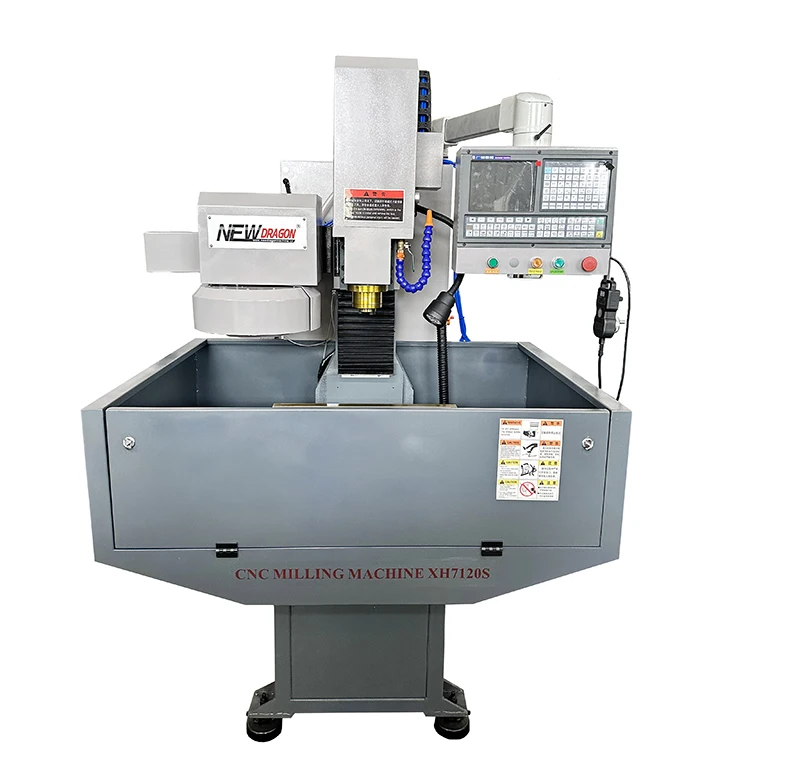
The product image directs users to read the operating manual and safety information before starting the machine. Use appropriate guarding, workholding, cutting tools, and personal protective measures for the job. Keep the operating area clear and follow applicable workplace requirements. Do not infer an unlisted certification, accessory, delivery term, or performance guarantee from this page. For demanding work, verify the complete setup, including tool projection, clamp position, workpiece balance, and machine condition, before beginning a machining cycle.
When evaluating the Combination Variable Speed Lathe and Milling MachineTU240X550mm, focus on the dimensions and tasks that matter most. Buyers who mainly turn longer workpieces may prioritize the 550 mm distance between centres. Buyers who need drilling or light milling should compare the listed head capacities, T-slot size, sleeve travel, and spindle-to-table distance with their fixture and tool plan. Buyers with limited room can also account for the listed packed dimensions and weight while planning delivery and installation. If the job requires a capability not stated in the supplied material, ask for confirmation rather than treating it as included.
For the Combination Variable Speed Lathe and Milling MachineTU240X550mm, verify the exact delivered configuration against the quotation, manual, and factory confirmation. A practical review can include a trial workpiece, the actual chuck or fixture, selected tool holders, cutter diameter, thread requirement, and local power supply. Check that the planned operation stays within the stated capacities and that the operator can safely control chip flow, clamping, tool changes, and measurement. Where a job is sensitive to finish or dimensional consistency, document the acceptance method before the work begins.
For a small workshop, combining operations can reduce handling between a turning setup and a separate drilling or milling setup. That benefit depends on the work sequence and setup time; it is not a promise of throughput. For a maintenance task, the listed speed ranges and thread ranges provide comparison points, while the final choice of tooling and cutting conditions remains the operator’s responsibility. The Combination Variable Speed Lathe and Milling MachineTU240X550mm is best evaluated against the actual component and process rather than against a broad product label.



 EN